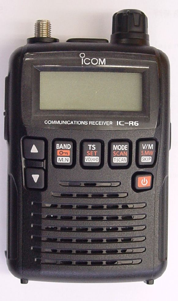

#Easy to use manual for icom ic r6 generator
receiving 1) c o n n e c t t h e s u p p l i e d a n t e n n a to a signal generator through an appropriate conecto.ĥ - 4 5-3 receive adjustments (continued) 1) select an adjustment item using /.2) s.ĥ - 3 adjustment receiver’s condition operation adjustment item value bar antenna (0.495 mhz) 1 note: this procedure (the step "1" and "2") must be done twice. 247.050 mhz (☑20 hz) 5-2 frequency adjustment 1) select an adjustment item using /. connect a frequency counter to "2nd lo" line on the rf unit as illustrated below.¤ key assignments for the adjustment mode equipment grade and range equi.ĥ - 2 adjustment receiver’s condition operation adjustment item value reference frequency 1 2) push and hold, ,and, turn the receiver’s power on. ¤ entering adjustment mode 1) connect the jig cable (see the illust below) to the jack. ĥ - 1 ¤ quitting adjustment mode turn the receiver’s power off. (for tuning voltage generation) o 118 beep beep sounds. O 116 ifcon if demodulator ic chip enable. Line name description i/o 114 func input. 4-5 cpu port allocation battery pack j500 d508 cp3 d509 cp4 dc sw chrg chrg c trl dc-dc conv r ese t logi c c trl +3s c trl ifv c trl chgc hv reset logic 3.3v +3s ifv pc.Ĥ - 5 4-5 cpu port allocation (continued) pin no. Wide fm/am mode the demodulated af signal is passed through the af filter (r316, r320 an.Ĥ - 4 4-4 voltage block diagram voltage from the power supply is routed to throughout the transceiver via regulators and switches. The 1st i.Ĥ-2 af circuits (logic unit) fm mode the demodulated af signal is passed through the de-emphasis circuit (r323 and c316) and af filter (q301), and then applied to the af amp (q300) through the af line sw (d300). 3rd if and demodulator circuits 1st if circuit (rf unit) the rx signal from the rf circuit is applied to the 1st if mixer (ic1) to be mixed with the 1st lo signal from the 1st lo vco (q528, q529, d105 and d106), resulting in the 266.7 mhz 1st if signal.The amplified signal is passed through the band sws (d71 and d72), and then applied to another rf amp (ic18). 15–29.995 mhz the rx signal from the antenna connector (chassis j1) is applied to the rf amp (q505) through the band sws (d63, d64 and d73), lpf and the hpf.


2) unsolder the 2 points from the speaker. Removing the logic unit 1) remove the dial knob, 2 nuts and 2 screws from the front panel. Removing the rear panel 1) remove the battery cover.

logic unit (top view) voltage limiter (d511) tone filter (ic200) cpu (ic1) ifv line sw (q104) logic3.3v regulator (q103) +5 v regulator (ic455) +3 v regulator (ic104) reset (ic3).Ģ - 2 dc-dc converter up converter circuit for tuning voltage.Table of contents section 1 specifications section 2 inside views section 3 disassembly instruction section 4 circuit descripiton 4-1 receiver circuits (rf unit). Do not expose the receiver to rain, snow. Never connect the receiver to an ac outlet or to a dc power supply that uses more than specified. This service manual describes the latest technical information for the ic-r6 communications receiver, at the time of publication.


 0 kommentar(er)
